“Kil’n It” or “Kiln Iot” (Kiln Internet of Things)
A friend of mine throws a little clay (does pottery) and has a used electric kiln with an analog meter on her thermocouple (device used to measure temperature in the kiln).
Based on my tinkering hobby, I thought a great project would be to build a digital, WiFi enabled, temperature sensor that could be plugged into the kiln’s thermocouple so she could have a digital display and be able to monitor it on her phone.
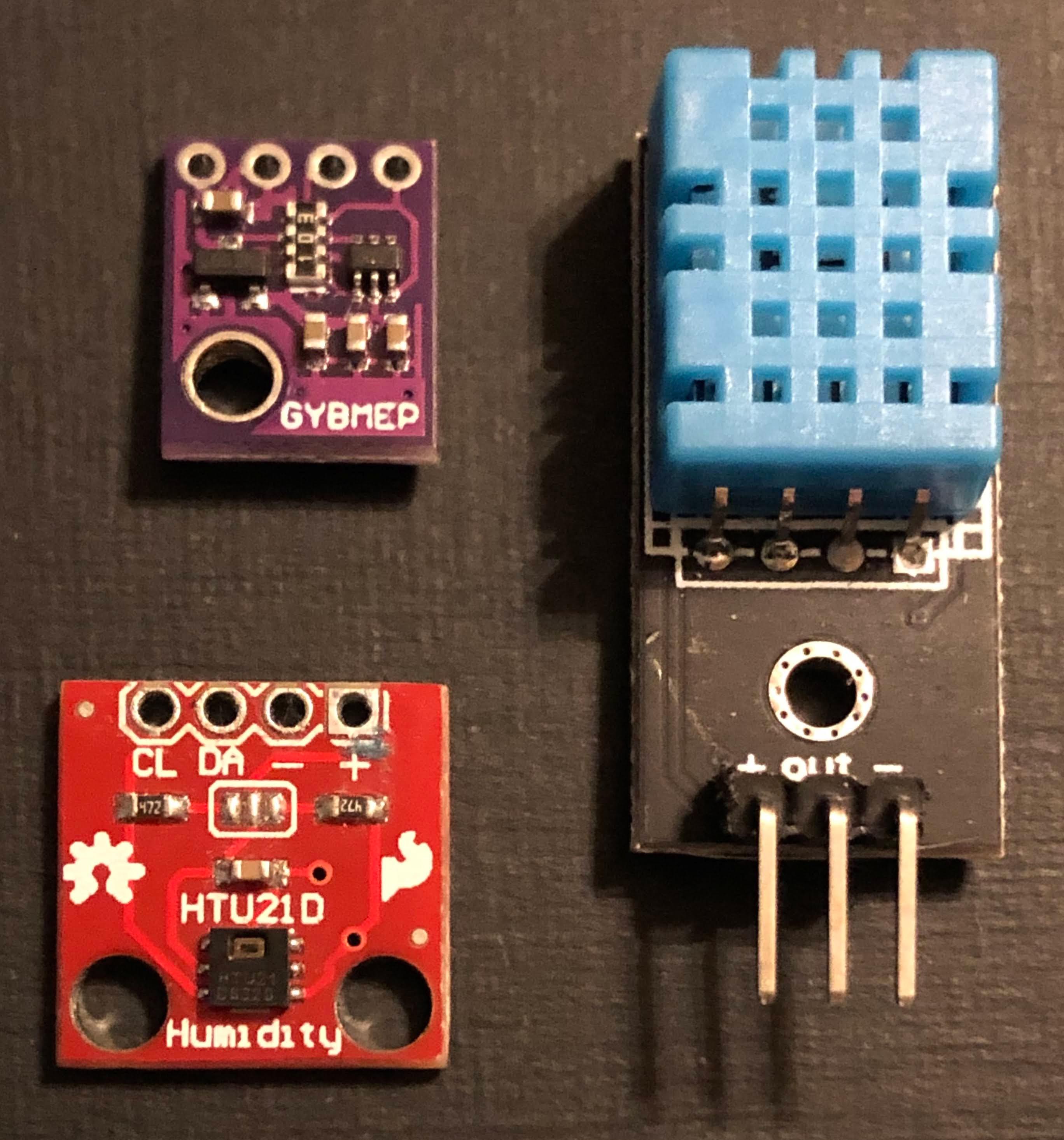
In my home automation projects, I’ve used inexpensive sensors (DHT11, HT221D, BME280, etc.) to monitor temperature and humidity in different areas of my house, patio, and shed
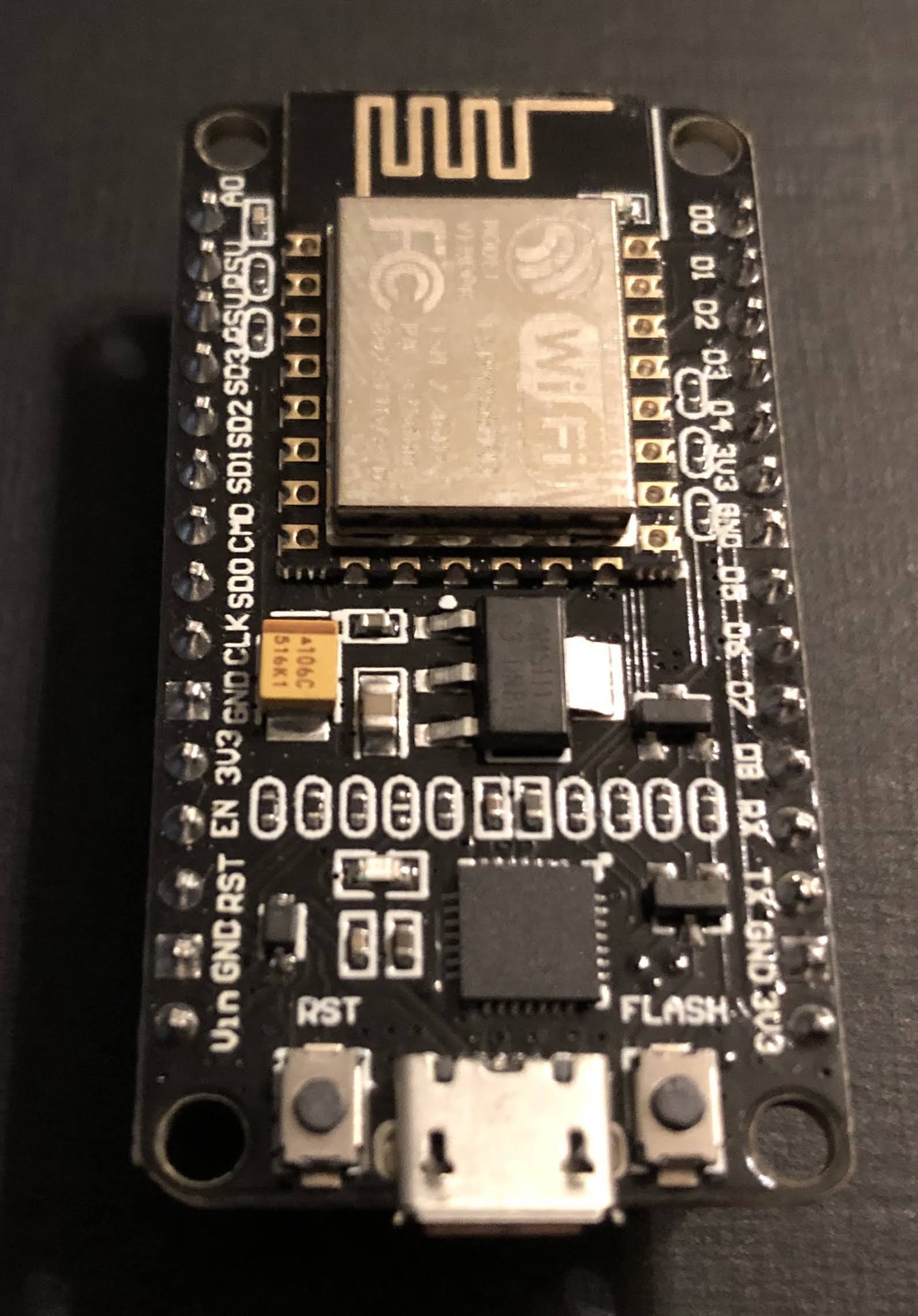
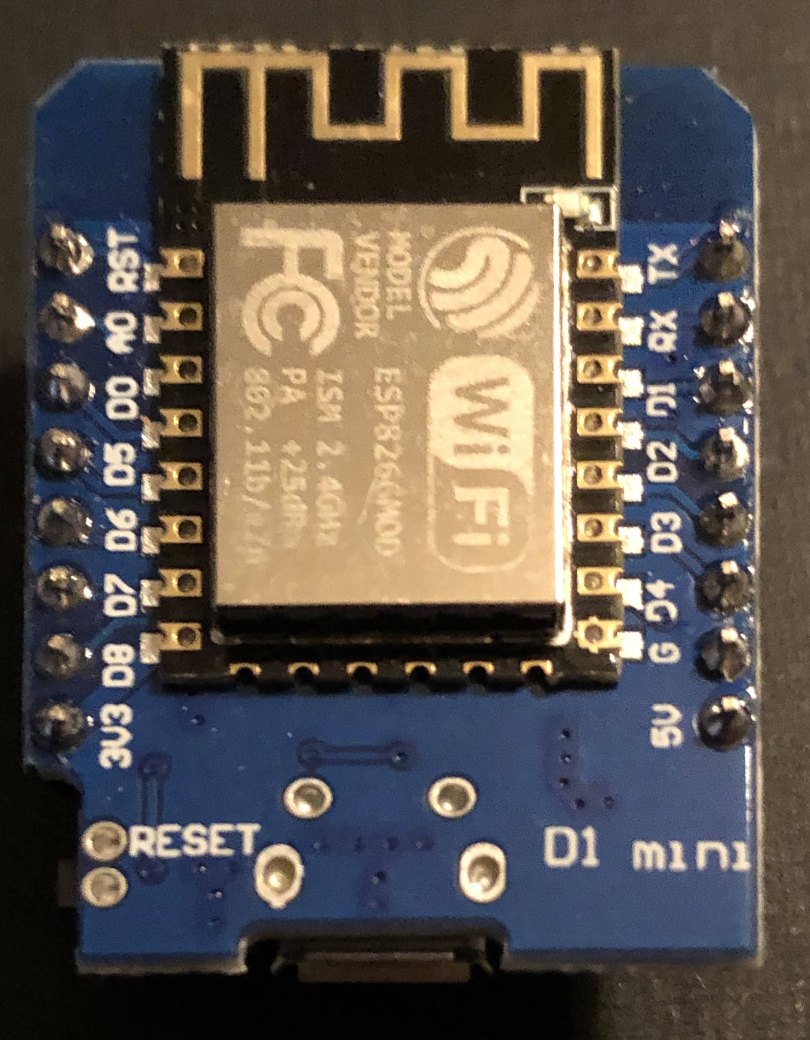
using NodeMCU and D1 Mini microcontrollers.
Based on my home monitoring I knew a kiln monitor could be done, but I’m measuring temps in livable environments (though it does get hot here in Texas!).
The challenge is that the sensors I use would burst into flames if you put them in a kiln! That’s why thermocouples are used in kilns… they can handle a couple thousand degree (oF) temps.
I learned that you need an amplifier to pick up this signal from the thermocouple and transform it into something a controller (with the right firmware (software)) can interpret into a temperature reading.
There are different types amplifiers (just google something like “thermocouple amplifier board”), but I went with the MAX31855. You can find breakout boards with this chip on them from a few different suppliers on Amazon.
The one I went with is from Adafruit, a NYC-based company that was only a couple of bucks more expensive than the others from companies I don’t know by name. Side note, I often buy electronics components from these unfamiliar companies on Amazon, including the controller I used in this project and the quality is often good enough for my tinkering, but if you want definitive quality, go with Adafruit.
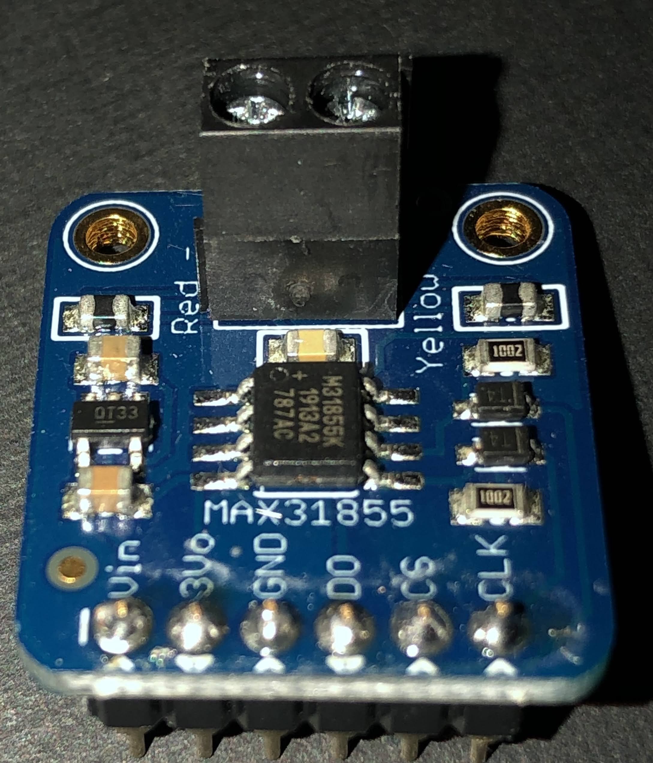
For this project I went with Adafruit because I knew the quality of this new-to-me board would be excellent and well worth the couple of dollars more.
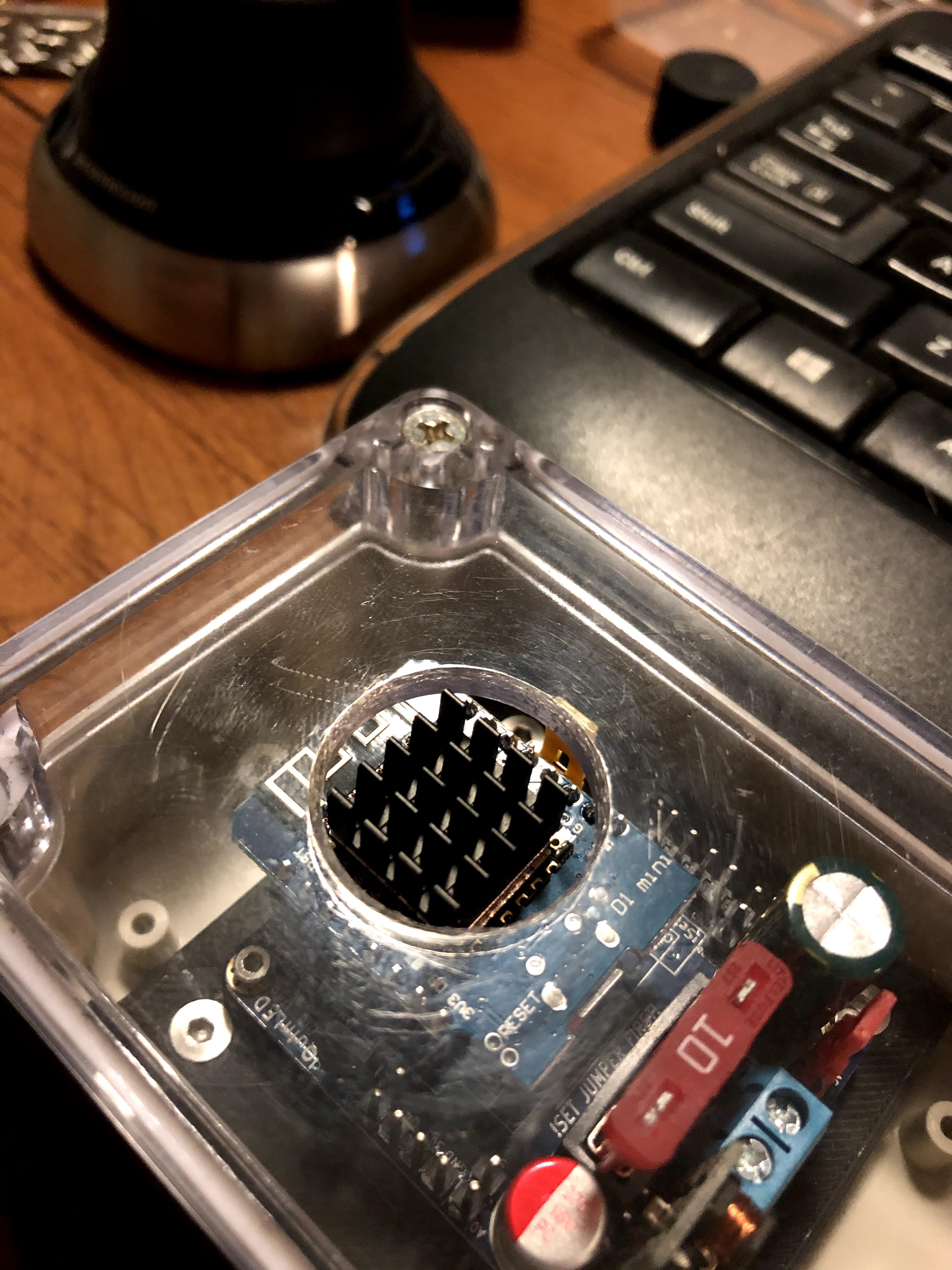
In the first iteration of this project, I soldered female headers to a printed circuit board so I could mount the controller (NodeMCU) and MAX31855 breakout board.
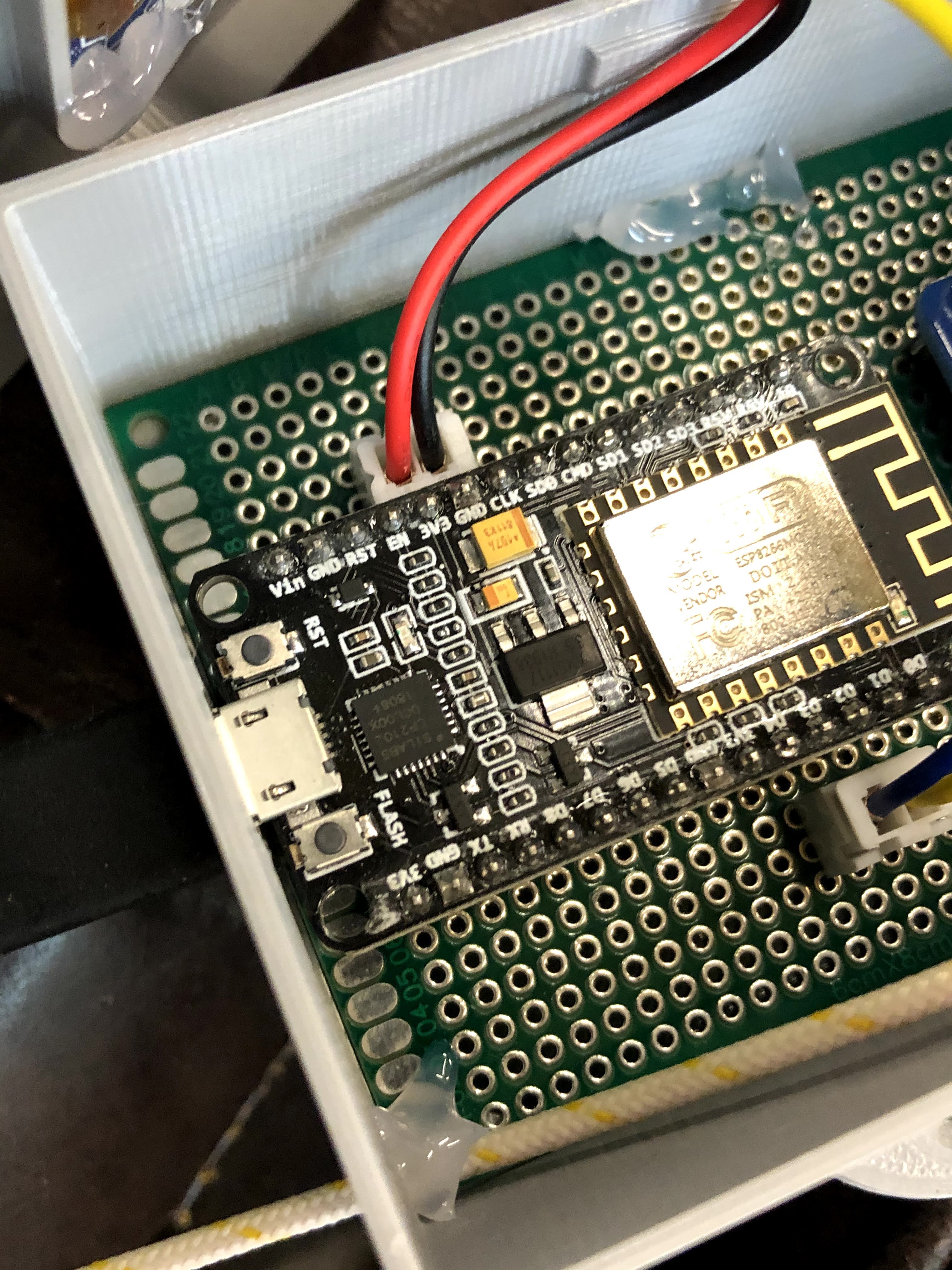
I then soldered the pins from the controller to the header for the amplifier board and connectors for the OLED display (SSD1306) (soldered wires are on the underside of the board in the pic below). I wired a thermocouple wire to the amp and was ready to program the controller.

At one point in my home automation adventures, I had the wild idea of learning to code so I could write my own programs. Through google and YouTube, I learned enough to put together some rudimentary programs that kinda worked, but I quickly realized that I was more interested in making things that work rather than getting behind the curtain and making the stuff (software) that makes stuff work. That’s when I discovered Tasmota, an excellent open source software that works with the controllers I use and can be customized for different applications. I’ve been using it almost exclusively in my projects since.
I downloaded Tasmota 8.1 for this project (the newest version at the time). In many cases, you can just flash the the precompiled binary (bin) file to the controller using a flashing tool like NodeMCU Pyflasher or Tasmotizer, but displays and the Max31855 aren’t supported in the base bin file (tasmota.bin).
This leaves a couple of options. You could flash the base bin file and then the sensors bin file and and then the displays bin file. The problem is these bin files can be pretty large (relatively speaking) and may not flash properly. You could try the lite version of the base bin file, which is pretty bare bones, and then try flashing the other two, but you may run into problems with that too.
That’s why I prefer to go a different route. I download the full Tasmota program and edit it in Arduino IDE (more recently PlatformIO). Though I’m no programmer by any stretch of the imagination, I have picked up just enough to understand a few things when looking at the Tasmota code (which is well documented throughout!).
In Tasmota, I can go ahead and set up my WiFi access (SSID and password to connect to a home network) and MQTT (so it can communicate with my home automation system (Home Assistant – another open source system that runs on a Raspberry Pi).
In Tasmota, I found the code for displays and uncommented those lines as well as uncommented the line for the MAX31855 sensor. Note: you’ll do most of the editing in the my_user_config.h file. See Travis’ (digiblurDIY) youtube video for an excellent tutorial. It is in PlatformIO rather than Arduino IDE, but the steps are basically the same, and he cleans the file up much better than I do to further reduce the size by disabling things he won’t be using. Note also that I did make one other change related to the SSD1306 display that I’ll explain in a bit.
I was then able to upload the firmware via Arduino IDE, and the controller was ready to set up.
I found the IP address of the controller since Tasmota made it discoverable on my home network. It’ll be in format of something like “192.168.1.12”, but the numbers from your network may vary. I use the Fing app, but you can log into your home router and find this too. Another way is to watch the serial monitor in Arduino IDE and it’ll show the IP address when the controller boots up.
I the put my controller’s IP address in a web browser and it connected to the controller via WiFi so that I could set up the display and temperature sensor (oh yeah, you have to first change the module type to “Generic” under the Configuration).
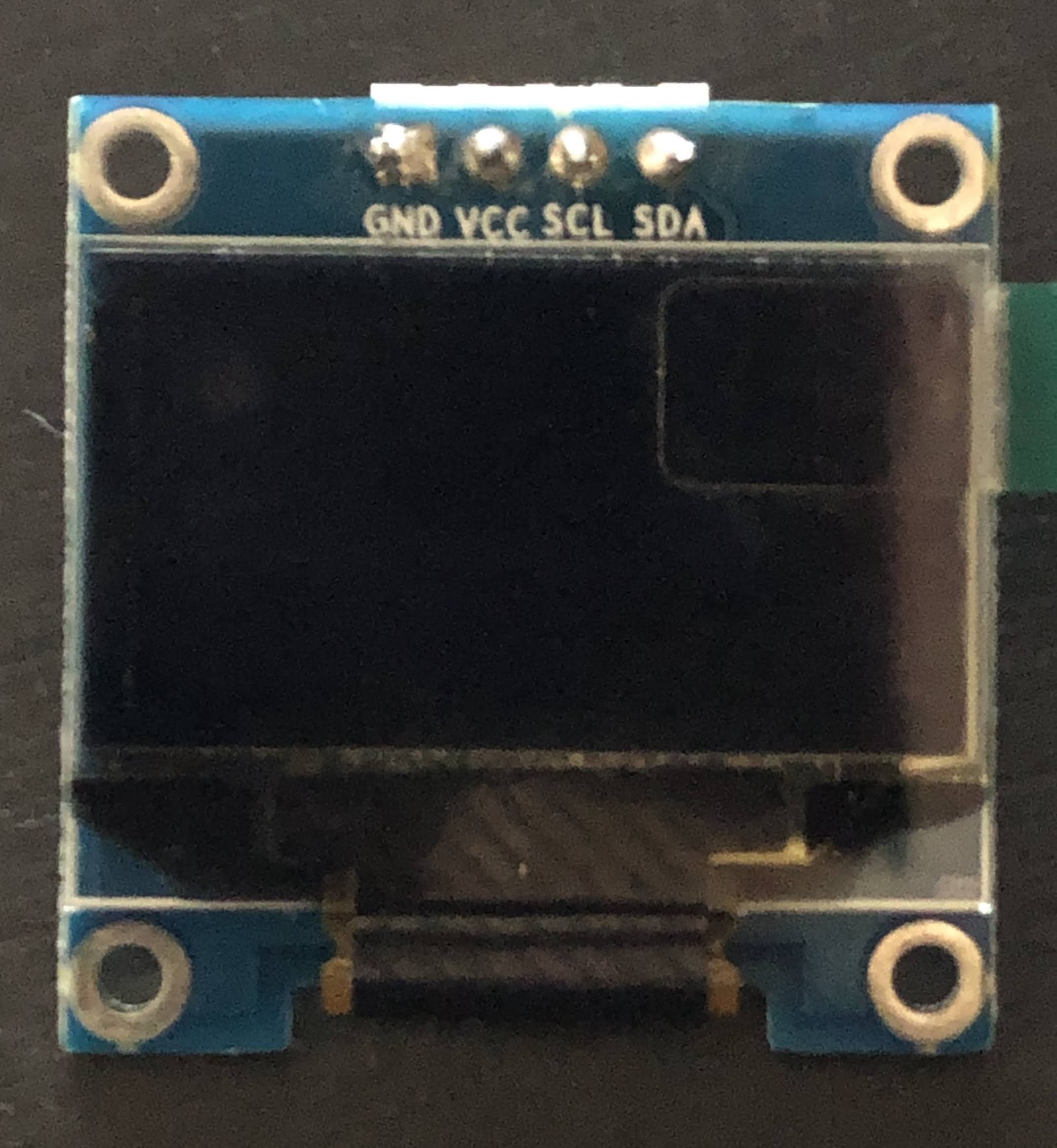
My SSD1306 display is an I2C device , so in the Tasmota web UI, I set GPIO4 to SDA and GPIO5 to SCL. Note that for my particular SSD1306, I had to go into the xdsp_02_ssd1306.ino file using the Arduino IDO and change the line “#define OLED_RESET 4” to “#define OLED_RESET -1” because Tasmota uses the Adafruit SSD1306 library which is designed for their SSD1306 that has the reset on pin 4. My particular display doesn’t use a reset pin, so I had to change it to -1.
The MAX31855 is a SPI device requiring three pins (Note: in Tasmota, it’s a softSPI rather than hardware SPI, so you don’t turn on (remove the backslashes before) SPI in the Tasmota code when editing it). In my application, I use GPIO12 for CS, GPIO14 for CLK, and GPIO15 for D0.
Once I set those up and restarted it, I was getting temperature readings through the Web UI from the thermocouple I had attached to the amplifier board. The pic below is a template and has a couple of of other features enabled.. read up on Tasmota if you want to know how to do templates, but the look is essentially the same as you’ll see using the Generic Module.

To get the display to work, you have to change some settings in Tasmota. Go to the Console in Tasmota and enter the following (without the quotation marks):
- “DisplayModel 2”
- This sets it up for a SSD1306 display
- “DisplayMode 0”
- So you can get the temperature reading as text to display
- You’ll also have to adjust the size of the text, and I created this Rule in Tasmota to do that (use the console for this too)
- Rule1 on tele-MAX31855#ProbeTemperature do DisplayText [f2p7x15y20]%value% F endon
Check out this link for more on Display commands in Tasmota.
From here, you can see the temperature on you computer or phone (I bookmark the Tasmota IP web portal for easy access) and turn the monitor on an off using the “Toggle” button. I’ve recently found the Tasmota command: WebButton Display On/Off (or whatever you want to call your web button instead of “Toggle”… just put the name after WebButton1 in the console command line).
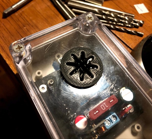
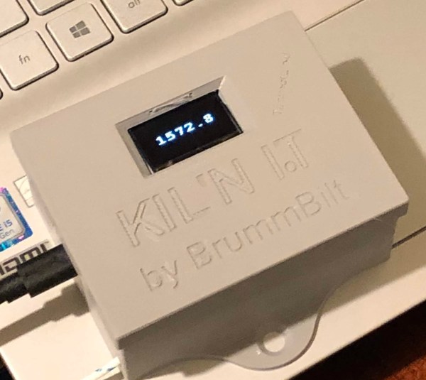
Once I had the controller set up and working I designed an enclosure (pic at top of this blog) in Fusion360 and printed it on my Ender 5 3-D printer. This took me way too many prints to get it how I wanted it, largely because I was still relatively new to Fusion 360 at that time. I won’t go into detail on my enclosure design, but feel free to contact me and I’ll be glad to share it with you… I’m working on tweaking that currently.
I did take the finished project over to my friends house and got it hooked up to her thermocouple and see the temp on the display. Unfortunately I wasn’t able to get it to connect to WiFi since where she has her kiln is in a building away from the house and they use a WiFi extender that I haven’t figured out how to work with in Tasmota yet. Maybe set up as the second access point??… other Tasmota users let me know your thoughts if you know how to do this.
She was nice enough to set me up with some free home brew (she and her husband make great beer… that Quad was incredible!), and black garlic (check out her company The Black garlic Company).
I’m still pretty pumped about making this kiln monitor since it was more complex than my household sensors I’ve made in the past. The free beer and black garlic just put the icing on the cake!
Here are some things I’m working on for version 2:
- Use D1 Mini instead of a NodeMCU.
- Use mini connectors so it’s easier to connect and disconnect the thermocouple (or connect a different thermocouple (for brewing or monitoring fermentation temps for example (though there are different sensors that are less expensive and easier to set up than a thermocouple).
- Use a printed circuit board with pin holes in parallel by row (makes soldering wires from controller pins to the display connectors and amplifier header easier). Ideally, I’ll put my big boy pants on someday and design a custom PCB.
I may update this blog post from time to time, but feel free to reach out if you have any questions I may be able to help with.